From about 1933 many American (and some European) radios were designed to operate directly from line voltage. These were called AC-DC or "transformer-less" sets. The voltage for heating the tube filaments was supplied directly from the line. Since the mains voltage in America is 117 AC and the tube filaments required only about 6 or 12v (25, 35, or 50v for many rectifier and output tubes) a resistor had to be provided to drop the excess mains voltage to the proper value to operate the filaments. The problem was simplified by connecting the tube filaments in series so that each filament acted as a resistor, dropping the voltage somewhat for the remaining filaments. In most cases, however, the line voltage was greater than the sum of the voltages required to heat the tube filaments and so an additional resistor was required to drop the excess voltage.
Example: A typical five tube set of the mid-1930's used three 6.3v tubes and two 25v tubes connected in series. The total voltage drop was (3 x 6.3) + (2 x 25) = 69v. Line voltage is 117v, Therefore, (117 - 69) = 48v must be dropped.
The resistor dropping the voltage often had to dissipate considerable power and so would become extremely hot. In many cases the resistor was built into the line cord, in the form of a resistance wire running the entire length of the cable ("resistance line cords"). Since the heat generated was distributed along the entire length of the cord, the cord became only moderately warm and so posed little danger. In other cases the resistor was built into a tube called a ballast tube. These were glass or metal tubes that looked like ordinary radio tubes and plugged into a socket on the chassis. They were often identified by a code, such as the following:
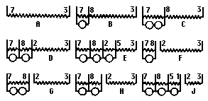
RMA BALLAST CODE
Example: type B-K-55-B-G
The
first letter (B) indicates a ballast tube but may not appear.
The second letter (K) indicates the type of pilot light used
in the set:
K - a 6-8v 0.15A bulb is used.
L - a 6-8v 0.25A bulb is
used.
In practice, any type of bulb can be used without harm to the set.
In the wiring diagram below the numbers stand for the prong connections of an octal socket.

With glass four-prong base ballast tubes, a much-used system was to have a number indicating the overall. resistance.
Example: type 185R4. The unit has an overall
resistance of 185 ohms. To convert this to the RMA code
multiply the resistance by 0.3 to obtain the voltage drop: 185
x 0.3 = 55v. The tube is equivalent to type KX55B.
The section of resistor across which the pilot lights are connected serve to provide an electrical path in case the lamps burn out. Also, it helps to absorb the surge in current that occurs after the set is turned on while the tubes are warming.
In the early 1940's tubes were designed with filaments that operated on higher voltages so that a set of these connected in series could operate off the line voltage with no dropping resistor being required.
Burned-out ballast tubes should not be replaced by resistors mounted in a set because a great deal of heat (15-25 watts) is generated.
In many cases the ballast tube or resistance line cord can be replaced with a silicon diode (e.g. 1N4004), with a zener diode (e.g. SK6X0) across the dial lamps to prevent them from burning out.

The power dissipated in a ballast tube or resistance line cord can be found by multiplying the voltage drop across them by the current drawn by the tube filaments.
Example: The five-tube set considered previously required a voltage drop of 48v. The current drawn by the tube filaments is 0.3A. The power dissipated is (48 x 0.3) = 14.4 watts.
Copyright © 2015 - All Rights Reserved - www.vcomp.co.uk